Polycom PathNavigator
The Polycom® gatekeeper product supplied was PathNavigator™ 5.1. This is dedicated software that offers a gatekeeper and additional services such as logging and billing. Before installing, check the minimum hardware and software system requirements for the version that you wish to install.
Pre-requisites
In order to set up a machine which meets the minimum requirements for this installation, the following steps should be taken while logged in as a user with administrator privileges. Some of these are necessary to provide the minimum system requirements for the PathNavigator™ software, while others are installed to ensure the security of the system, and to provide remote maintenance tools.
- Install Windows 2000 Server.
- Install any Service Packs for Windows 2000 Server.
- Use Start>Settings>Control Panel>Add/Remove Programs>Add/Remove Windows Components to remove any services that you do not wish to enable (by default the Windows server will offer various network, file and printing services that could negatively interact with such services that you have already configured on your network).
- Install an anti-virus program.
- Connect the server to the network.
- Update the anti-virus.
- Install firewall protection software.
- Visit Windows Update site, scan for updates, install all security updates, patches and service packs, etc. This requires a number of system reboots.
- Install VNC on to the machine, for remote access (optional).
- Extract the supplied zipped files and folders to default destination.
- Find the required files (mdoc_typ.exe, Jetinstall.exe and JetSP5_W2K.exe) in the C:\PNBuild\PathNavigator5_1System_Update_Resources folder.
- Install mdoc_typ.doc (and reboot the system).
- Install Jetinstall.exe (and reboot the system). Although the installation instructions ask for JetSP5_W2K.exe, the set-up indicated that a newer version had already been installed, so this was not installed.
- Run the file: C:\PNBuild\PathNavigator5_1/setup.exe
Accessing the program
From another Windows-based machine (Windows 98 or later), open Internet Explorer (5.5 or above) and enter http://<IP_address>/pathnavigator (substituting the IP address of the gatekeeper host machine for <IP address>).
This should start the web access for the PathNavigator™, and you will be presented with the login screen. Enter the user name ‘Admin’, and you will be prompted with the opportunity to enter a password for administration of the system.
By default the Admin password is null (i.e. there is no admin password). This can be rectified by selecting the Configuration button, and then User Administration from the left-hand buttons, then Users – no other users will have been configured, so select the edit button from the top-right and enter a password and click ‘OK’.
PathNavigator™ configuration
Once installed, the PathNavigator™ is administered by logging in using Internet Explorer (v5.5+). This can be done from the same server that is running the PathNavigator™, or from a remote location that can access the server. Once logged in, configuration changes are made using tabbed web pages which have check-boxes and pop-up windows to carry out the various configuration tasks.
The PathNavigator™ has a sophisticated list of parameters that can be altered. This configuration guide considers only those necessary for compliance and inter-working with the JVCS. The configuration described below does not include inter-working with a Cisco® H.323 proxy (or MCM), a Cisco® PIX firewall, or any other firewall/security solution. The gatekeeper administrator, of course, needs to address the network security of the gatekeeper itself and the terminals that are registered with it.
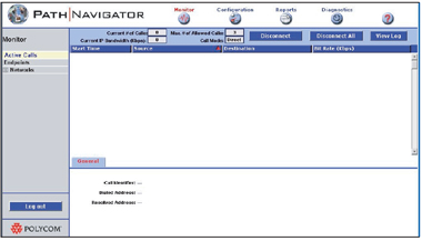
Figure 7. PathNavigator™ – Opening Page
The first page seen is the list of current Active Calls. Obviously there will be no active calls during initial configuration. The button names and their functions should be self-explanatory. Select the Configuration button at the top of the page.
The configuration page has a number of tabs. These allow for configuration of the various parameters necessary for the PathNavigator™ to function. The Configuration tabs have parameters organised into headings and sub-headings. Selecting the ‘heading’ will display the contents of the first sub-heading on the list.
The Submit button should be pressed before leaving a page in order to save any configuration changes. These will take effect immediately – there is no need to re-start the gatekeeper.
General Configuration

Figure 8. Path Navigator™ Configuration>General
The General Configuration page contains information about the nature of the licence held. The only configurable items on this page are the gatekeeper identifier and description. The identifier (which will always be preceded with PN) is used in communications between endpoints on the network and the gatekeeper. The description is used in a Polycom® environment for the readable name that the Global Management System will use when managing PathNavigator™. It is up to the gatekeeper manager what terms are entered here.
Registration Policy
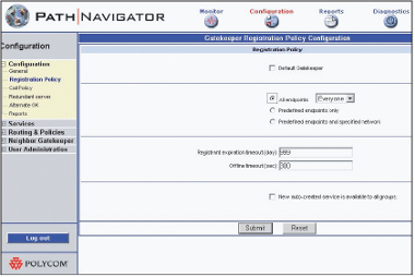
Figure 9. PathNavigator™ Configuration>Registration Policy
Do not check Default gatekeeper unless you wish all gatekeeper discovery messages to be answered by the gatekeeper. Because this may allow access to the gatekeeper by unauthorised endpoints, it is recommended that this item is left unchecked. This will mean that endpoints will need to be told explicitly about the gatekeeper’s IP address in their configuration.
It is possible to add a further level of security by selecting the option to admit pre-defined endpoints only. By default ‘Everyone’ can register. It is recommended that Predefined endpoints only is checked as a security measure. It will then be necessary to define which endpoints are allowed to register with the gatekeeper, and this process is described in below.
It is possible to allow access to register with the gatekeeper according to endpoint group membership (see below, but this configuration assumes no groups have been defined, apart from the default ‘Everyone’ group.
Registrant expiration timeout can be set at any amount between 1 and 999 days. The default is 30 days. If ‘999’ is entered, this effectively makes the ‘registration’ permanent. Here, the word ‘registration’ has a slightly different meaning to that normally used in an H.323 environment. It means that the gatekeeper will retain the information about the endpoint — even if it is off-line — for the number of days specified. Managers can use their own discretion, but might wish to allow for the summer holidays, for example.
The Offline timeout is the period that the gatekeeper will wait for a ‘keep-alive’ message from the endpoint before considering it ‘offline’. The default is 300 seconds (i.e. five minutes) and this should be adequate for most situations.
New auto-created service is available to all groups – this item can be left unchecked in most simple configurations. It only applies if user groups have been defined and MCU or gateway services are available.
The current status of endpoints is shown on the Monitor page, Endpoints tab. While an endpoint is online and registered with the gatekeeper, the endpoint will have a grey ball in the left hand column (see Figure 10). While actually in a call, the ball will turn green. A lightning strike will appear if a regular ‘keep-alive’ message is not received from the endpoint – the point that this lightning strike will appear will be dependent on the value entered in the ‘Offline timeout’ box (described above).
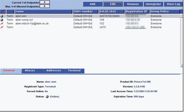
Figure 10. PathNavigator™ Monitor>Endpoints
Call policy
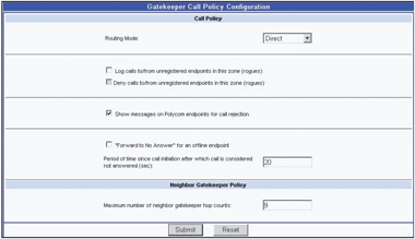
Figure 11. PathNavigator™ Configuration>Call Policy
Two routing modes are available: routed, or direct. ‘Direct’ (call set-up is not mediated by the gatekeeper) should be selected.
The options regarding unregistered endpoints in this zone (rogues) should be left unchecked in most college configurations. If you have Polycom® endpoints you can check the option for Show messages on Polycom endpoints for call rejection to get more meaningful error messages displayed if a call is rejected.
“Forward to No Answer” for an offline endpoint – leave this unchecked in most circumstances. The default value for considering a call unanswered can be left as it is (20 seconds), unless there is a local reason to change it.
Maximum number of neighbor gatekeeper hop counts: – the number of times an LRQ will be passed from one gatekeeper to another before the request dies. The default value of 3 is too low for international calls to be resolved using the GDS (described in !!REFERENCE The Global Dialing Scheme https://community.ja.net/library/videoconferencing-booking-service/globa... 3 above), which is adopted by many NREN managers worldwide. The recommendation is for this figure to be at least 9, to allow for any unforeseen circumstances.
Redundant Server
This is for situations where a live back-up PathNavigator™ server is in place and will not be relevant to most JANET-connected organisations. A redundant server will duplicate the parameters of the usual gatekeeper.
Alternate GK
This is for situations where there is more than one gatekeeper on a network, each administering different zones. If the endpoints are sending out gatekeeper LRQs then they will normally be answered by the ‘default’ gatekeeper. It is possible for an alternate gatekeeper to answer the requests if the default gatekeeper is unreachable for any reason. However, it is currently recommended, for most situations, that endpoints are told specifically about a particular gatekeeper, and the gatekeeper answers requests from pre-defined endpoints only. As most JANET-connected organisations will be operating only one gatekeeper for the foreseeable future, this page can be left unchanged.
Reports
The PathNavigator™ produces reports on call failures and other events. The reports available include CDRs (Customer Data Reports), network reports and WAN (Wide Area Network) link utilisation reports. The values entered in these fields are at the discretion of the gatekeeper manager. Once archived, the reports can be found at:
drive:\program files\polycom\pathnavigator\reports\ on the server.
Services
Currently the JVCS offers centralised access to well-provisioned network gateways and MCU services, so this section will not be relevant. Unless there is a specific local reason not to do so, all services should be disabled.
Routing and policies
Group Policy
The PathNavigator™ gatekeeper is supplied with one default group called ‘Everyone’ to which all endpoints belong. It is possible to define other groups in order to apply different policies (such as bandwidth allocation) to different machines. However, for most simple H.323 implementations the default situation will apply and will be the most appropriate set-up (i.e. there is no need to define any other groups).
Should you wish to define additional groups, change the parameters of a group, or delete a group, you do so by using the Add / Edit / Remove buttons. However, during testing it was found to be impossible to delete a group once it had been created.
If you have created more than one group you can assign a particular terminal to a group when using the add endpoint or edit endpoint buttons available on the Monitor/Endpoints page (see below).
Least Cost Routing
This will not apply to most JANET-connected organisations using Janet Videoconferencing.
Network topology
Network(s) that endpoints are to register from must be defined here in order to ensure the successful operation of the PathNavigator™ gatekeeper. The scenario described below assumes no local ISDN gateway or other services are available. This section follows the ordering of the pages in the Networks section of the Configuration pages (although this ordering does not always seem to follow the actual steps needed for the configuration).
Summary
This page will not be populated until the following sections have been configured. On first use it displays the default network, ‘Internet/VPN’. This pre-defined network must remain in the configuration. When other networks have been defined by the gatekeeper manager, these will also be displayed on this summary page.
Select a network in this list to see a summary of the parameters associated with that particular network displayed in the pane below. This lower pane has four tabs to show different aspects of the network selected, and these networks and their associated parameters can be defined in the rest of the pages in this Network Topology section.
The summary page has a report button, which can be used to generate a report for all defined networks or for a specific defined network. An example report for a network called ‘any 323’ is shown in Figure 12. This network is a logical network that contains defined physical IP networks. In this example two distinct IP networks have been defined. In tests, a Class C IP sub-net and a network consisting of a single machine were successfully defined and united as a single PathNavigator™ network. The following sections cover the process of defining these PathNavigator™ networks.

Figure 12. PathNavigator™S Configuration>Routing and Policies>Summary>Report
Networks

Figure 13. Path Navigator™ Configuration>Routing and Polices>Networks>Add/Edit
To ‘tell the gatekeeper about’ networks that endpoints in its zone are on, select this page and then select Add.
General Configuration
The Network name will be any name that makes sense for the gatekeeper manager. Endpoints within this network are in this zone should be checked.Country Code will be 044 (within the UK). Area Code – enter the POTS (Plain Old Telephone System) local exchange code here. # of digits in phone: in the UK, enter ‘6’.
Auto assign ISDN number configuration
Direct Inward Dial (DID) assignment – leave both values as zero.Gateway extension dialling – all values can be left blank.
IP Network Configuration
Default group policy – The only choice here will be ‘Everyone’ unless local policy groups have been defined.Default Least Cost Routing table – ‘None’.
WAN Links

Figure 14. PathNavigator™ Configuration>Routing and Policies>WAN Links>Add/Edit
On this page it is necessary to define the link from the IP network(s) that have been defined using the Networks page (see above), to JANET (and thence to the Internet). To do this select Internet/VPN from the drop-down list of networks at the top of the page; then click the Add button to the right of the screen. The page that then appears is very similar to the Edit page in Figure 14 (above). It contains fields for:
WAN Link Name – enter ‘Link to JANET’ (or similar phrase to identify the nature of this link).
First network in the path – select the network name used to identify the local PathNavigator network that has previously been defined (‘any h323’ in the example above).
Other network(s) reached through this WAN Link: – ‘None’, as there have been no other networks defined for this gatekeeper. This parameter would display other networks if they had been defined for a more complex scenario, and if that network were reached through the WAN link, this would need to be explicitly configured here. In most cases there will be a single network (which may consist of more than one subnets) and a single link.
Max. Bandwidth (Kbps) – select a figure that is suitable for the WAN link specified. This figure is not the total bandwidth of the WAN link, but the portion that is available for H.323 calls. This figure will reflect the number of simultaneous H.323 calls that the WAN link can support, and also the bandwidth of the link itself and the throughput of other traffic that the WAN link supports. In the test case, the figure of 2000 was selected.
Max. Bit Rate (Kbps) – this is the maximum bandwidth available to each call made through this link.
Network Addresses
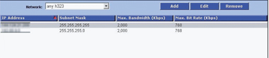
Figure 15. PathNavigator™ Configuration>Routing and Policies>Network Addresses>Add/Edit
The name of the network that was added previously — in the example ‘any h323’ — will automatically appear in the drop-down list at the top of this page. This page is now used to define the IP addresses, or subnets, that are part of that logical network.
Local IP networks and subnets are added by use of the Add / Edit / Remove buttons at the top right of the page. The parameters that need to be entered for each LAN (local area network) to be added are: IP Address, Subnet Mask, Max Bandwidth (kbps) and Max Bit rate per call (kbps).
It is possible to add Class C IP subnets, or smaller subnets by judicious use of subnet masking. It is also possible to add a network that consists of a single machine by using its IP address and the subnet mask 255.255.255.255. In the example shown in Figure 15, all H.323 equipment resides on one class C subnet (although the endpoints are distributed around the campus using VLANs), and a single machine is also specified as part of this gatekeeper’s network.
ISDN Range
There is no need to configure this page.
Neighbor gatekeeper
Neighbor

Figure 16. PathNavigator™ Configuration>Neighbor Gatekeepers>Neighbors>Add/Edit
The Polycom® gatekeeper does not recognise a hierarchical gatekeeper regime. However, for inter-working with the JVCS-IP Global Dialling Scheme, it is necessary to define only one neighbour – the JVCS directory gatekeeper. This national directory gatekeeper resolves E.164 addresses that are not in the local gatekeeper’s zone. By naming the JVCS directory gatekeeper as the neighbour, any E.164 addresses that are not resolvable by this PathNavigator™ gatekeeper will be passed to the directory gatekeeper. It is also necessary for the JVCS-MC to tell the national directory gatekeeper about this local gatekeeper – its IP address and its E.164 number – and this is done when the local zone address is issued).
To add the national directory gatekeeper as a neighbour, select Add and enter the details of the national directory gatekeeper. The Add page is very similar to the Edit page in Figure 16.
The values to enter are as follows:
Description: a text description of the neighbour; e.g. ‘national gatekeeper’ (or similar).
IP: the numeric address of the national directory gatekeeper to replace the aaa.bbb.ccc.ddd in the illustration – this will have been supplied by the JVCS-MC on request.
Prefix: leave blank (there is no need to stipulate any value, as the PathNavigator™ will pass any unresolvable E.164 address to this neighbour).
# of digits to strip in prefix: 0 (i.e. the complete E.164 address will be passed to the directory gatekeeper).
Prepending string: leave blank (so that nothing is added to the E.164 number).
Port: 1719 (the default for inter-gatekeeper communication)
Of course, in practice there are actually two directory gatekeepers, for resilience. So it is necessary to repeat this process in order to enter the address of the second national directory gatekeeper, whose address and name will also be supplied by the JVCS-MC on registration for the IP service. Two neighbours will then be defined without a prefix and the PathNavigator™ will send a location request to both neighbours simultaneously. It will then act on the information supplied by the first directory gatekeeper to reply successfully.
Local Zone prefix
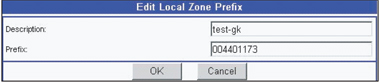
Figure 17. PathNavigator™ Configuration>Neighbor Gatekeepers>Local Zone prefixes>Add/Edit
This page is used to tell the gatekeeper about the prefix that is ascribed to its own zone. This prefix will be of the form 0044xxxxx and is supplied, on request, by the JVCS-MC. The prefix is unique to this gatekeeper and IP address, and will be held by the national directory gatekeeper for E.164 address resolution. This prefix number will be stripped from incoming calls before the address is resolved to a local endpoint. There will usually be only one entry on this page. To add your local zone prefix use Add. There are only two values to be entered:
Description: whatever you have named your gatekeeper.
Prefix: 0044xxxxx (substituting the 5 digit number that has been supplied by the JVCS-MC for the ‘x’s).
User administration
Groups
You can create users who can access various elements of the PathNavigator™. These users can belong to one of three default groups, each of which has different levels of rights and privileges on the PathNavigator™ server. The default situation is that there is one user (Admin) who has full administrative rights and is a member of the group ‘Administrator’. For most organisations this will be adequate, but it is possible to create further users with various rights if there is a local need to do so. As well as Administrators, two other groups already exist by default. These are: ‘Operator’ and ‘AR Billing’.
In order to manage additional user groups, use the Add / Edit / Remove buttons on the right hand side of the screen. These buttons allow you to create or edit existing or additional groups, which can have permissions added or withdrawn by using the pop-up checklists of rights, and saving any changes. The Summary button provides a summary of the ‘Read’ and ‘Modify’ rights of the various groups. Highlight a group and click Summary to see what a group’s current rights are.
Users
It is also possible to add and edit users of the system. This is simply a matter of creating a user name, password and ascribing the user to a group.
Monitor section
Monitoring
The Monitor pages give statistics on current usage for endpoints, networks administered by this gatekeeper, and WAN links. Each of these pages allows the administrator to see the current state of use of endpoints, networks and WAN links that the gatekeeper is aware of. They are not a log of usage but a snapshot of the current situation (logs are generated by using the Reports button, although the View Log button on the Monitor>Endpoints page will provide information on recent messages between the endpoint selected and the gatekeeper).
Adding Endpoints
Although it is possible to allow ‘Everyone’ to register with the PathNavigator™ gatekeeper, this approach is not recommended as it does not provide the level of security desirable in an educational organisation. For this reason it is recommended that during normal operation the registration policy defined at Configuration>Registration Policy should be set to ‘Pre-defined endpoints’.
However, if the policy is first defined as ‘Everyone’ and then the allowed endpoints are registered (by configuring each terminal to register with this gatekeeper), when the Policy setting is changed to be ‘Pre-defined endpoints’, those endpoints which are currently registered will stay registered. This is the easiest way to add a number of terminals to the gatekeeper’s list of pre-defined endpoints, as it saves having to manually enter them.
Once the registration policy has been changed from ‘Everyone’ to ‘Pre-defined endpoints’ (on the Configuration>Registration Policy page) any other endpoints that try to register with the gatekeeper will be rejected, and if any further H.323 terminals are added to the network they will have to be manually defined on this page, by selecting Add.
To add an endpoint using this interface, choose the endpoint type from the drop-down list at the top of the page. For JVCS-IP use, only terminals should be registered with the local gatekeeper. The fields should be completed as follows:
- Internal IP Address: If the IP address is static enter it here, or indicate that the IP address is obtained through DHCP.
- Call signaling port: leave as the default, 1720.
- Force to online status: leave unchecked.
- Country code/Area code/Number: leave blank and set the drop-down list box to read ‘Use default from network’.
- Group policy: ‘Everyone’.
- Forward… options: all can be left blank.
- Alias type: For the first row, select E.164 and enter the terminal’s extension number as the Alias value. For most organisations this will be a three-digit number arbitrarily applied by the network manager. The terminal should also be configured to know about its own extension number. When configuring the terminal, be sure to use only the extension number, not the entire E.164 address. The Key Alias field can be ignored.
- For the second Alias type/value pair it is suggested that an H.323ID is selected and this should be of the form jvcs-reg-name@collegedomain.ac.uk – where the JVCS registered name of the terminal is substituted before the @ and the domain name (as used in local e-mails) is substituted for the college name – e.g. aber-penglais-hol@aber.ac.uk.
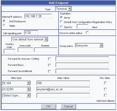
Figure 18. PathNavigator™ Monitor>Endpoints>Add/Edit
Reports and diagnostics
PathNavigator™ also has the potential to record usage statistics by endpoint, network or WAN link. These reports can generate a .csv (comma separated values) file if required, for further analysis. The Diagnostics pages appear to be intended for short term analysis and trouble shooting. Please refer to the gatekeeper’s help pages for more details on how to generate, configure and use these reporting and diagnostic features.
Polycom PathNavigator™ references
- Product Support: http://www.polycom.com > Support > Network Management > PathNavigator
- Product Overview: http://www.polycom.com > Products and Services >Network Conferencing Solutions> Management and Scheduling > Polycom PathNavigator


