Appendix B - Analogue and digital signals
B.1 Analogue Signals
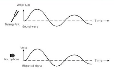
Human senses respond to analogue signals. If a tuning fork is struck it vibrates to create a characteristic sound wave as illustrated in Figure B. 1. The wave is a typical analogue signal and it would gradually decay to zero as the mechanical energy in the fork is expended as radiated sound. A microphone is a device that converts sound energy into electrical energy. A microphone placed near to a resonant tuning fork would generate an electrical signal as shown below. The electrical signal is similar in shape to the original sound wave and it is a typical analogue signal.
Figure B. 1: Analogue Signals
B.2 Digital Signals
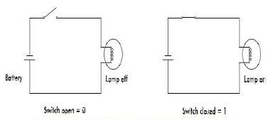
An electrical switch can either be OFF or ON i.e. open or closed. In Figure B.2 the switch is open and the lamp is off. With the switch closed the lamp illuminates. A single switch therefore has 2 states, OFF and ON. This can be represented by OFF=0 and ON =1. If there are two switches, we can have four or 2^2 possible states:
| Both OFF i.e. | 00 |
| The first ON the second OFF i.e. | 10 |
| The first OFF the second ON i.e. | 01 |
| Both ON i.e. | 11 |
Figure B. 2: The Two Binary States Represented by a Lamp
If there are three switches, there can be eight or 2^3 possible states:
| A | B | C | The equivalent analogue number |
| 0 | 0 | 0 | |
| 0 | 0 | 1 | 1 |
| 0 | 1 | 0 | 2 |
| 0 | 1 | 1 | 3 |
| 1 | 0 | 0 | 4 |
| 1 | 0 | 1 | 5 |
| 1 | 1 | 0 | 6 |
| 1 | 1 | 1 | 7 |
So with 3 switches there are 8 possible combinations. It will be noticed that a 1 in the column below switch C represents 1 or 2^0, under switch B, 2 or 2^1 and under switch A, 4 or 2^2. This system of numbering based on the power of 2’s is termed binary. A further column to the left of A would indicate an even higher power of two i.e. a 1 in this column would represent 2^3 (8) and so on for additional columns.
B.3 Sampling
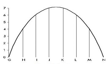
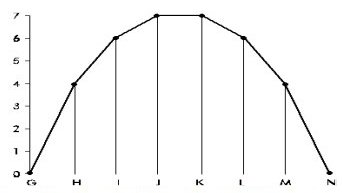
If a portion of the microphone’s analogue electrical signal (from Figure B. 1) is sampled as illustrated in Figure B. 3. Between the points G to N, the amplitude is seen to vary between 0 and 7.
Figure B. 3: Sampling.
Sampling produces these values:
| At | G | 0 |
| H | 4 | |
| I | 6 | |
| J | 7 | |
| K | 7 | |
| L | 6 | |
| M | 4 | |
| N | 0 |
However, these analogue levels may also be represented as an alternative in binary number form using the 3 switches A, B and C:
| A | B | C | ||
| G | 0 | 0 | 0 | 0 |
| H | 4 | 1 | 0 | 0 |
| I | 6 | 1 | 1 | 0 |
| J | 7 | 1 | 1 | 1 |
| K | 7 | 1 | 1 | 1 |
| L | 6 | 1 | 1 | 0 |
| M | 4 | 1 | 0 | 0 |
| N | 0 | 0 | 0 | 0 |
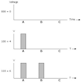
As an alternative to 3 switches A, B and C it is possible to use electronics to generate voltage pulses. The absence of a pulse at positions A, B or C represents 0.
A pulse in position A represents 4, at B, 2 and at C, 1. This is illustrated in Figure B. 4.
Figure B. 4: Voltage Pulses Representing Digital Values
B.4 Analogue to Digital Conversion
If an analogue electrical signal e.g. the signal from a microphone, is sampled, the samples converted to binary numbers and then pulses equivalent to the binary numbers generated (similar to Figure B. 4), the process is termed analogue to digital conversion. There is an electronic device that can perform this analogue to digital conversion called an Analogue to Digital Converter (ADC) which is an essential component of all digital systems.
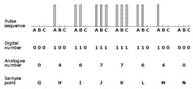
A comparison can be made between the sample values for our original microphone signal, their digital (or binary) numbers and the resulting digital pulse sequence. Figure B. 5 illustrates this.
Figure B. 5: Comparison between Sampling values and the digital representation
Human senses respond to analogue not digital signals; in other words, we hear the noise emitted by a tuning fork as an analogue stimulus. The digital equivalent (i.e. a series of pulses) would be unrecognisable, so although digital sound signals may have advantages for travelling over a network they have to be converted back to their analogue equivalent to be meaningful to a listener. Exactly the same is true for visual information. The human eye like the ear responds to analogue stimuli so devices are needed to reconvert digital vision signals back to analogue. This is achieved by Digital to Analogue Converters (DACs). ADC’s and DAC’s are two essential building blocks of digitisation.
Figure B. 6 shows the result of Digital to Analogue conversion for our original microphone signal. As can be seen the reconstruction is not exact, if Figure B. 4 and Figure B. 1 are compared, the smooth curved edge of the original sine wave has been clipped into a series of straight lines. This is a disadvantage of digitisation. Digitisation Errors have been introduced. These errors can be minimised and made practically invisible by sampling at a high enough speed and having a sufficiently large number of reference values so providing sufficient resolution or accuracy for the sampling.
Figure B. 6: Reconstructed Signal showing Digitisation Errors
With high speed, high resolution sampling, there will be many more sampling points and so the digitised, clipped reconstructed edge will more accurately mimic the original smooth curve.
The speed at which an analogue signal is sampled is known as the Clock Speed. The accuracy of the digitisation depends on the length of the digital number, (or the number of switches/pulses involved). A 3 bit system can resolve eight levels i.e. (23 or 2x2x2). An 8 bit system can resolve 28 or 2x2x2x2x2x2x2x2 or 256 different levels, whereas a 24 bit system can resolve 224 or 256x256x256 or 16,777,216 levels.
Digital signals have many advantages over their analogue equivalent. On an analogue video recorder, every time a tape (or cassette) is copied the copy suffers a reduction in quality. In broadcasting, six or more generation copying is common place. With digital tape copying the sixth generation copy will be almost identical to the original with little or no degradation. This is only because the presence or absence of pulses needs to be detected. The magnitude of the pulses (unlike analogue signals) is of no consequence.
Signal processing, e.g. compression of television signals for videoconferencing, is achieved much more easily in the digital domain. By using signal compression, many more digital television channels can be squeezed into the space originally taken by one analogue channel. This may not be seen to be an advantage by everyone but is particularly important for satellite transmission where bandwidth (or channel space) is at a premium and very expensive.

